- A back yard assembles itself as you scroll — 1,288 parts across 15 build stages, drawn live in the browser rather than played as a video.
- One parametric spec is the single source of truth. It feeds a real-time WebGL scene and, via an export, a Blender/Cycles render of the identical model. Neither renderer defines geometry, so the two can never drift apart.
- The spec cites the Alberta Building Code inline — guard heights, footing depth, joist spacing — so the model is correct by construction for an audience that includes people who build decks for a living.
- Every part carries
{stage, order, from}. That metadata, not keyframing, is what turns a model into a build sequence. Nobody animated 119 deck boards. - The export ships 401 pre-computed camera positions rather than the camera algorithm, which removes an entire category of "why don't these two match" bugs.
- Cycles costs ~36 seconds a frame; WebGL costs ~16 milliseconds. So iterate in WebGL and render the hero in Cycles — the cheap renderer is the authoring environment.
- With CAD as the source instead of a hand-written spec, the geometry pipeline is solved tooling. Assembly order is the part CAD can't give you — and it's the whole difference between a 3D model and a story.
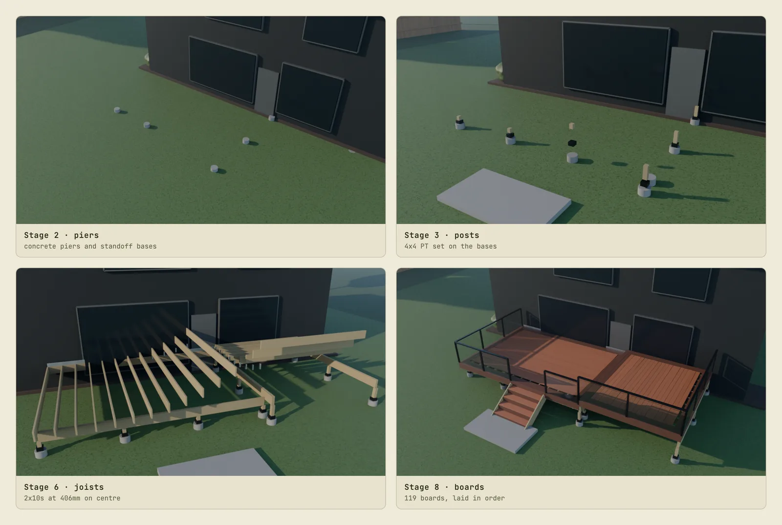
Scroll down a page and a back yard builds itself. Piers go in the ground first, then posts, then the beam and the joists, then boards run across the frame and a picture-frame border closes the edge. A fence rises along the property line. Concrete gets formed, poured, finished, and the forms come away again. Beds go in, then planting, then sod.
Nothing about that is a video. It's a real-time 3D scene, assembled from 1,288 individual parts, and the scroll position is the only input. It runs on the site we built for a Calgary deck and fence builder. The same model, exported, rebuilds itself inside Blender for the photoreal hero shot — because it is not a second model, it's the same one.
This is how it's built, what it cost, and where the approach goes when the source of truth stops being a hand-written spec and starts being the client's own CAD.
The rule that makes the whole thing work
There's one architectural decision here, and everything else follows from it.
A parametric specification defines the yard. A builder turns that specification into discrete parts. Two renderers consume those parts: a real-time WebGL scene for the site, and a Blender/Cycles scene for photoreal stills.
The renderers never define geometry. They can't — they have no dimensions of their own to work from. Which means the two can never disagree about what's being built, no matter how much either one changes.
The tempting alternative is what most studios do: model it once in Blender for the pretty renders, then rebuild a simplified version in Three.js for the web. That works exactly until the first change request. Move the stair, widen the deck, and now you're doing it twice and hoping they still match. Two weeks later they don't, and nobody knows which one is right.
The spec is a building code document that happens to be executable
Here's the top of the specification file. Read the comments rather than the numbers:
// src/deck-spec.js
/**
 * Code basis (Calgary / Alberta Building Code, verified 2026-08-04):
 *   - Building permit required above 600mm to deck surface. This deck is 850mm.
 *   - Guard height 900mm where surface is 600mm–1800mm above grade.
 *     (1070mm only at >=1800mm.)
 *   - Maximum guard opening 100mm — satisfied by glass infill panels.
 *   - Footings min 250mm diameter, bearing below Calgary frost depth of ~1200mm.
 *   - Joists at 406mm (16") on centre — also AZEK's maximum for perpendicular
 *     board runs. A 45-degree board run would require 305mm (12").
 *   - Stair rise 125–200mm, run min 255mm. Ours: 170mm rise / 280mm run.
 */
Every one of those numbers was checked against the actual code before a single triangle was drawn, and each constant in the file carries its justification next to it:
export const RAILING = {
  height: 900,          // ABC: 900mm for 600–1800mm above grade
  postSize: 51,         // 2" black aluminium
  postSpacingMax: 1830,
  glassThickness: 12,
  glassInset: 30,       // reveal between glass edge and post
};

export const FOOTING = {
  diameter: 250,        // 10" min
  depthBelowGrade: 1200,// below Calgary frost
  baseHeight: 90,       // black standoff post base — keeps end grain off concrete
};
This matters more than it looks, and the reason is commercial rather than technical.
The audience for a deck builder's website includes people who build decks. A contractor looks at a rendering the way a copy editor looks at a paragraph — the errors surface before anything else does. A guard at the wrong height, joists spaced too far apart for the board run, a post base sitting timber directly on concrete, a guard running straight across a stair opening where code requires it to stop. Any one of those turns your beautiful animation into evidence that you don't know what you're selling.
Encoding the code basis in the spec means the model is correct by construction. There is no separate review step where somebody eyeballs the render and hopes. If the guard is 900mm in the file, it's 900mm in the WebGL scene and 900mm in the Blender render, and it is 900mm because a line in a comment says why.
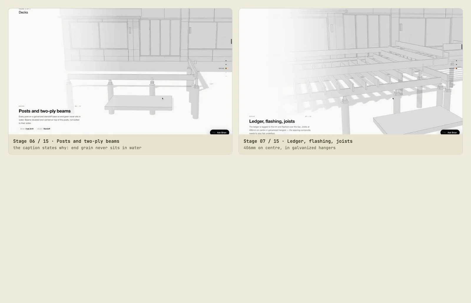
The transferable idea: when you model something a professional audience will scrutinise, put the standard in the source and cite it inline. Every industry has its version — clearances, tolerances, load ratings, accessibility dimensions. That comment block is the difference between a visualisation and a claim you can defend.
Parts, not a model
The second decision is that nothing here is a "3D model of a deck." It's a pile of parts that know things about themselves.
// src/deck-build.js
/**
 * Every part carries { stage, order, from } so the scroll timeline can bring it
 * in independently. Nothing here is decorative: if it exists in the model it
 * exists on a real deck, and it sits where code says it sits.
 */
const add = (mesh, stage, order, from, exit) => {
  mesh.userData = { ...(mesh.userData||{}), stage, order, from, trade: TRADE };
  mesh.userData.finalPos = mesh.position.clone();
  if (exit) mesh.userData.exit = exit;   // { stage, order?, to }
  group.add(mesh);
  parts.push(mesh);
  return mesh;
};
Four pieces of metadata do all the work:
stage— which phase of the build it belongs to, out of fifteen.order— where inside that stage it lands, so 119 deck boards arrive in sequence rather than all at once.from— where it flies in from, so parts arrive from a direction that makes physical sense.trade— deck, fence, concrete, landscape or furnishing. The decks service page filters todeckso a visitor reading about decks doesn't watch fence post-holes appear.
That last number is the one worth sitting with. Of 1,288 parts, 1,129 are boxes. A deck is boards and lumber and posts, which is to say a deck is boxes — and a scene made almost entirely of the same primitive is dramatically cheaper to build, to instance and to draw than one made of imported meshes. The performance budget was won at the modelling stage, before a line of render code existed.
The fifteen stages
| Stage | Trade | Parts | Scroll span |
|---|---|---|---|
site |
ground | — | 0.00 – 0.06 |
piers |
fence, deck | 34 | 0.04 – 0.12 |
fence-posts |
fence | 46 | 0.12 – 0.18 |
fence-rails |
fence | 38 | 0.17 – 0.24 |
fence-boards |
fence | 350 | 0.23 – 0.30 |
deck-frame |
deck | 26 | 0.29 – 0.38 |
deck-joists |
deck | 54 | 0.36 – 0.46 |
deck-boards |
deck | 119 | 0.45 – 0.58 |
concrete-base |
concrete | 65 | 0.57 – 0.65 |
concrete-pour |
concrete | 127 | 0.64 – 0.71 |
concrete-finish |
concrete | 14 | 0.70 – 0.77 |
land-beds |
landscape | 56 | 0.76 – 0.82 |
land-planting |
landscape | 202 | 0.81 – 0.89 |
land-sod |
landscape | 67 | 0.88 – 0.95 |
reveal |
furnishing | 90 | 0.94 – 1.00 |
Two things in that table are deliberate. The spans overlap — piers begin at 0.04 while the site stage is still finishing at 0.06 — because on a real site trades overlap, and hard cuts between phases read as a slideshow. And the part counts are wildly uneven: 350 fence boards against 14 concrete-finish parts. Even distribution would have been easier to write and completely wrong, because a fence genuinely is mostly boards.
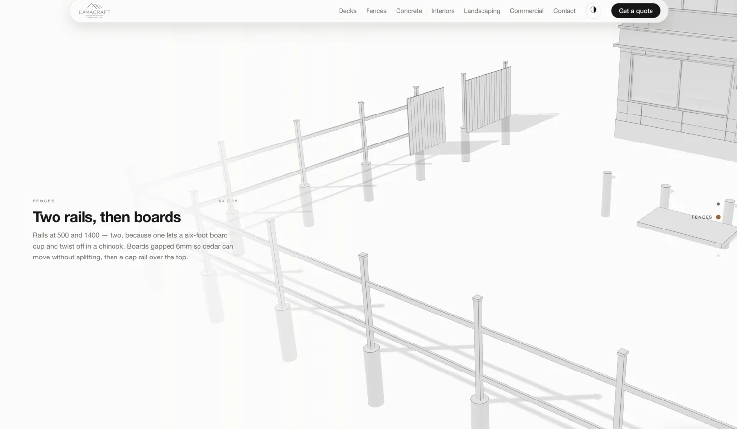
Scroll position drives assembly
With parts tagged, the timeline becomes arithmetic rather than animation. Each stage owns a slice of scroll; each part owns a slot inside its stage.
// src/scene.js
const PART_WINDOW = 0.45; // how much of a stage a single part takes to land

function setProgress(p) {
  const t = clamp01(p);
  for (const mesh of parts_) {
    const { _s, _e, _from, order, finalPos } = mesh.userData;
    const sp = clamp01((t - _s) / Math.max(1e-6, _e - _s));   // progress in stage
    const startAt = order * (1 - PART_WINDOW);
    const local = clamp01((sp - startAt) / PART_WINDOW);
    if (local <= 0) { mesh.visible = false; continue; }
    // ... interpolate from `_from` to `finalPos`, ease, done
  }
}
PART_WINDOW at 0.45 is the entire feel of the thing. Each part takes 45% of its stage to travel, which means parts overlap heavily — while board sixty is still landing, boards sixty-one through seventy are already on their way. Set it to 1.0 and every part in a stage moves in unison, which reads as a shrink-wrapped group rather than a crew working. Set it near zero and parts snap in one at a time, which is both slow and mechanical.
There's no keyframing anywhere. Nobody animated 119 deck boards. The boards animate themselves because each one knows its own position in the sequence, which is why adding a level or widening the deck needs no animation work at all — new parts arrive with the same rules.
Temporary parts
The detail that convinced the client the model understood construction is small and slightly pedantic.
Concrete needs forms. Forms are there while the pour cures, and then they come off. An animation that leaves the formwork standing forever is wrong in a way every trades person notices instantly.
// forms come off once the slab has cured
const STRIP_FORM = { stage: 'concrete-finish', order: 0.15, to: [0, 900, 0] };
Any part can carry an exit: a stage at which it leaves, and a direction to leave in. The forms rise away during the concrete-finish stage. Shoring behaves the same way.
It's a handful of lines. It's also the difference between a sequence that shows a building process and one that shows objects appearing.
The camera problem, and a solution worth stealing
Both renderers need to move the camera along the same path. The obvious approach — define the path in the WebGL scene, then reimplement the same interpolation in Python — is the obvious approach and it's wrong. Two implementations of a curve will diverge, and you'll be comparing renders trying to work out why the Blender shot sits four degrees off.
So the export doesn't ship the path. It ships the answer:
// src/scene.js — exportParts()
// Sample the camera path densely so Blender replays the identical move
// instead of reimplementing the interpolation and drifting from it.
const SAMPLES = 401;
const cameraSamples = Array.from({ length: SAMPLES }, (_, i) => {
  const c = cameraAt(i / (SAMPLES - 1));
  return { pos: orbitToPos(c), focus: c.focus };
});
401 pre-computed camera positions, baked at export. Blender reads them and moves between them. There is no second implementation of anything, so there is nothing to drift.
The same principle covers the easing. PART_WINDOW = 0.45 in the JavaScript has a twin in the Python:
# blender/build_deck.py
EASE_WINDOW = 0.45          # matches PART_WINDOW in scene.js
That's the one genuine duplication in the system, and it's commented as such so the next person knows the two must move together. Everything else crosses the boundary as data.
The generalisable rule: when two systems must agree, ship computed values across the boundary, not the algorithm that computes them. Sampling is cheap; two implementations of the same maths is a bug with a delay fuse.
What each renderer is actually for
The reason to keep both comes down to one measured number.
Blender/Cycles renders this scene at roughly 36 seconds per frame at 1600px and 128 samples. Eight stills is about six minutes. A 120-frame animation is over an hour, per attempt, before you've seen whether the camera move works.
The WebGL scene renders it at 60fps, for free, while you drag a slider.
| Real-time WebGL | Blender / Cycles | |
|---|---|---|
| Time per frame | ~16ms | ~36 seconds at 1600px / 128 samples |
| Eight stills | instant | about six minutes |
| 120-frame animation | instant | over an hour, per attempt |
| Change a dimension | reload | re-export, re-render |
| Shows the client | three options in a call | one option, tomorrow |
| Best at | iteration, interaction, shipping | light transport, final hero |
So the division of labour is decided by arithmetic, not preference. Iterate in WebGL — that's where the spec lives, where a dimension change is instant, and where the client can be shown three options in a call. Render in Cycles only once, for the hero still, where light transport genuinely beats real-time shading.
This is the part clients find counterintuitive: the "cheap" real-time version is the authoring environment, and the "expensive" photoreal version is a downstream export. Most 3D pipelines have that relationship backwards, and pay for it in every revision round.
Making it survive a phone
Real-time 3D on the web is easy to demo and hard to ship, and almost all of the difficulty is mobile.
The specific problem here: the camera is composed for a 16:9 landscape frame. Put that same fixed vertical field of view on a portrait phone canvas and you get a narrow vertical column through the middle of the yard — the deck is off-frame, and the visitor sees a fence post and some grass.
// src/scene.js — resize()
// On a portrait canvas the fixed vertical FOV would slice the yard to a narrow
// column. Widen the vertical FOV so the frame keeps (cover x) the horizontal
// extent the 16:9 camera was composed for.
if (opts.portraitFit && camera.aspect < 1) {
  const baseHalfH = Math.atan(Math.tan(degToRad(34) / 2) * (16 / 9));
  const cover = opts.portraitCover ?? 0.95;
  const v = 2 * Math.atan(Math.tan(baseHalfH) * cover / camera.aspect);
  camera.fov = Math.min(70, radToDeg(v));
} else {
  camera.fov = 34;
}
Rather than recomposing every camera for portrait, the field of view is derived from the aspect ratio so the frame keeps the horizontal coverage the shot was designed around. The 70-degree cap stops it turning into a fish-eye on very narrow screens.
Alongside that, the things that decide whether a 3D section is usable rather than merely impressive:
- Pause offscreen. An IntersectionObserver stops rendering when the canvas isn't in view. A WebGL canvas quietly drawing at 60fps below the fold is a battery complaint waiting to happen.
- Shorten the scroll. The desktop journey runs long by design. On a phone the same distance is exhausting, so the sections are compressed and a skip control is offered.
- Respect reduced motion. A scroll-driven build sequence is exactly the sort of thing that makes some people ill. There has to be a still frame path.
- Budget the download. Because this is generated geometry rather than imported meshes, there is no model to download at all — the scene is built in the browser from a specification measured in kilobytes.
That last point is the quiet advantage of the parametric approach and it only exists because we didn't start from a mesh.
Where this goes: CAD as the source of truth
Everything above was hand-specified, because the client had no drawings — the deck in the animation is a designed one. That's the norm for a residential builder and it's why the spec file exists.
But plenty of businesses have the drawings already. Manufacturers have SolidWorks assemblies. Builders and architects have Revit and IFC models. Fabricators have STEP files. In those cases the hand-written spec is replaced by something far richer, and the interesting work moves.
Steps 1 through 4 are a solved tooling problem. CAD geometry is usually NURBS or solid bodies and has to be tessellated into triangles; the result is far denser than the web needs, so it gets decimated, welded and instanced; then it's compressed into glTF with Draco or meshopt geometry compression and KTX2 textures. There is mature tooling for every one of those stages, and the output is a file a browser can stream.
| Source | What it is | What it carries beyond shape | Route to the web |
|---|---|---|---|
| IFC | Open BIM exchange | Full property sets — type, material, fire rating, system | IFC → glTF with property preservation |
| Revit | BIM authoring | Families, parameters, phasing, schedules | Export IFC or glTF; phasing is the gift here |
| SolidWorks / STEP | Solid modelling | Assembly tree, part numbers, mates | Tessellate → decimate → glTF |
| Rhino / Grasshopper | NURBS + parametric | The parametric definition itself | Direct glTF export; Grasshopper can drive variants |
| SketchUp | Lightweight modelling | Groups, components, layers | glTF export; usually needs cleanup |
The column that matters is the third one. Geometry is the easy part — every one of those formats can be turned into triangles a browser will draw. What separates a useful pipeline from a pretty one is whether the meaning survives: that this component is a specific part number, that these walls belong to phase two, that this assembly has a variant.
The interesting part is what CAD carries that a mesh doesn't. A Revit or IFC model isn't a shape — it's a database of objects that know what they are. This wall is a wall, of this assembly type, with this fire rating. This fastener is that part number. Those property sets survive into glTF as extras if you preserve them deliberately, and once they do, the model can be interrogated rather than merely displayed: click a component and get its specification, filter by system, price a variant.
And here is the honest part, which is step 5. CAD tells you what every part is. It does not tell you what order a crew installs them in. Assembly order is not a property of the drawing — it's knowledge that lives with the people who do the work, and capturing it is a conversation with a foreman, not an import setting. Our fifteen stages came from how a yard actually gets built: you can't pour concrete before the piers, you don't sod before the beds, forms come off after the cure.
That sequencing is the entire difference between a 3D model and a story. Everything left of it is tooling. It's also, conveniently, the part a client can't get from a software vendor, which is what makes it worth paying an agency for.
What it's actually good for
Worth being clear-eyed: a scroll-driven build sequence is not right for most websites. It's right when the process is the product.
It's also not always the right way to put 3D on a page. For a jewellery client we did the opposite — 360 pre-rendered frames swapped as an image source rather than a live scene, because the subject was one object that never changed and photoreal fidelity mattered more than interactivity. Pre-rendered frames win when the thing is fixed and beautiful. Real-time geometry wins when the thing is assembled, because the assembly is the point and a frame sequence can't be filtered, re-ordered or reconfigured.
It earns its place when what you sell is complicated enough that customers don't understand what they're buying — a build, an installation, a fabricated assembly. When the sequence itself is the differentiator, because a competitor showing a finished photo can't demonstrate that they know how it goes together. When the audience includes specifiers who will judge you on whether the details are right. And when it replaces a page of text that nobody reads with something that answers "what will actually happen at my house" in fifteen seconds of scrolling.
It doesn't earn its place on a service where the process is uninteresting or the buyer doesn't care. Sometimes the answer is a good photograph.
Where CAD-driven versions get genuinely interesting is configuration. Once the geometry is parametric — as ours is, and as any CAD assembly already is — the visitor can change it. Pick a decking colour, a guard style, a size, and watch the same build sequence reassemble with those choices. That's a configurator with a build story attached, and it's a materially different thing from a spinning product viewer, because it shows the customer their thing being made.
If you only remember four things
One source of truth, two renderers. The moment geometry is defined in more than one place, the versions start drifting and you're maintaining a disagreement.
Ship computed values, not algorithms, across a boundary. 401 camera samples exported at build time removed an entire category of "why don't these match" bugs.
Metadata is what turns a model into a sequence. {stage, order, from} on every part is what makes the thing tell a story, and it's four fields.
The standard belongs in the source. A comment citing the building code next to the constant it justifies is the difference between a render and a claim you can defend in front of someone who does the work.
If you sell something that gets built, installed, or assembled — and especially if you already have the CAD for it — we should talk. The hard part isn't the graphics. It's knowing what order it goes together in, and that's a conversation, not a file format.
Keep reading
- Claude Code 2026: AI website development from the CLI
- OLVR ring scroll: Rolex 3D via Shopify custom development
Work with Rough Works
Need a partner for your next site? We're a Vancouver-based digital agency building websites and AI-enhanced experiences for brands across Canada and the United States. Start a project →